Hey folks, Phil Zito here and welcome back. In this post, we are going to be shifting gears from our sales conversation that we've been having the past several posts and we are now going to be focusing in on some more technical concepts. So, this post is going to be making sense of electrical concepts without becoming an electrician.
We're going to be looking at Ohms Law, we're going to be talking about the relationship between current, resistance, and voltage. We're going to talk about why you see the volt amperes drop on transformers as you turn on more devices and turn on more outputs. So, we're going to cover a lot of concepts related to electricity.
What do you need to know in regard to electricity? This is one of the things that back when I was first starting off in the field, I was trying to figure out my place in the field. I went and applied for an electrical license and I started the process of pursuing that, but I gave up on that because I realized it wasn't necessary. It's kind of where a lot of folks end up.
You come into this industry from a variety of different backgrounds. Some folks come from a mechanical background, other folks come from an electrical, some from an IT, some from a military background like myself. Really figuring out what you need to know, that is one of the biggest challenges.
If you talk to someone with an electrical background, they're going to tell you that you really need to understand all of this electrical stuff because they lean on that, but you may not need to know all that stuff. Then if you go under someone with a mechanical background, they're going to tell you to pursue an apprenticeship, really become a mechanic, understand the systems first. In reality, I've never changed a compressor in almost 20 years now. And I'll tell you that a lot of what you would learn, that path is unnecessary.
So, the purpose of this post is to really explore some key concepts and understand how all this ties together.
You have Ohms Law: volts, current, resistance. These come together to form what is known as Ohms Law. We'll talk about the relationship here in regards to how this all works.
What we have to understand in a traditional building automation system, we have a transformer, and this transformer, quite simply, transforms power. Typically, it's what is called a step-down transformer. It's going to step down voltage, typically 120 Volts AC, to 24 Volts AC and in the process, this transformer is going to have what we know as VA’s or volt amperes.
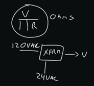
So, one of the things I first want to talk about here with Ohms Law, and just electrical concepts in general, is you have volts, that's one measurement, electrons flowing across the wire, you have “I” which is known in the term of amps, and then you have “R” which is known in the term of Ohms, as resistance.
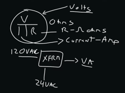
So, volt amperes is quite simply the ability to transfer this power from the transformer to the end device.
Now what does that look like? So, we have a transformer, and you have a primary side, which is the incoming power to the transformer, especially with a step-down transformer, and then you have the secondary side, which is where we're primarily concerned as controls folks. The secondary side is where we have our 24 volts AC. Typically, we'll have transformers that are rated for 40 VA, or 100 VA, etc.
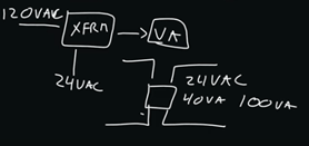
What happens is, as this building automation controller on the transformer feeds from the secondary side to the controller, then this controller is going to have, potentially, internally sourced voltage. This voltage is potentially used to drive devices. So, you'll see where controllers have internally sourced voltage to drive what are known as coils, and you'll also see where transformers go directly to the control device, like maybe an actuator, and they actually enable the motor of the actuator to be driven.
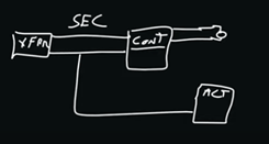
Now, what happens is that whenever you are using a transformer, and this transformer is going to a resistive load, a motor impedes the transfer of electrons. So, what happens is electrons, volts, are the power and this transformer’s providing that power. When that power hits this device, it starts to impede the flow of the electrons, and since volt amperes, VA, is current x volts, obviously the electrons decrease, and our VA is going to decrease the capacity of the transformer to provide that power to drive devices as we activate more devices off the secondary.
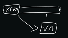
So, you have this one concept right here, where this actuated load causes the transformer to have less VA, to have less power, to be able to then drive devices. Now what's happening is, you will see that on a controller, like if we were to bring up a controller catalog sheet, the controller catalog sheet would say that an unloaded controller maybe requires 14 VA but requires 40 VA when it's fully loaded. That's because the controller is sourcing voltage to drive outputs. As it drives outputs, those outputs have certain amp ratings and voltage ratings, which then decrease the VA capacity of the transformer.
So, to put that in another way, is if you've ever used a drip hose to do a garden, and you've run water to that drip hose. As you go from drip nozzle to drip nozzle to drip nozzle, the pressure gradually reduces to the point where you go from a potentially strong drip to a very weak drip further down that drip hose line. Well, that's the same concept of a transformer and decrease in VA. As you put more resistive loads onto that circuit, then we are going to see a decrease in power ability to the point where it can get so low, that devices cannot fully actuate or, in a worst-case scenario, controllers actually start to go online and offline. That's why sizing your transformers for an accurate VA loading is critically important.
We've covered these concepts of a transformer, we've talked about VA, Ohms Law and somewhat the relationship between these things. So, if I were to blow out Ohms Law even more, you would see that how it works is kind of like this.
So, current x resistance = voltage.
If I want to get current, I am going to divide voltage by resistance, and will equal current.
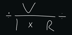
So, that's kind of how all of this comes together and how this equation works. You have two variables so you can solve for the one variable.
Continuing along with this concept of voltage, current, and resistance. We have what is called a circuit, and we typically use circuits extensively in building automation. We use circuits to typically energize coils, and we will use these coils to change the states of contacts. This is a very, very common approach to a lot of building automation problems. You want to turn on a fan, we energize a relay coil, and we allow voltage to pass through the contacts, and those contacts will energize a starter, energize a motor, etc.
So, we have a circuit with a coil, and that coil gets energized. When that coil gets energized, it changes the state of the contacts, which are these metal contacts, that open and close based on the energization of this coil. As those contacts change state, they either create a complete circuit to allow voltage to pass through, or they don't.
So, we would have something like a normally open set of contacts and as a coil gets energized, that normally open set of contacts closes. Then we have hot and ground as a circuit and somewhere in between, we will have a device, maybe like a starter, and that starter will get energized. As that starter gets energized, that then allows a fan to turn on.

Now to pull in that coil, requires a certain amount of amperage. To energize starters directly, requires even more amperage. That's where some of this VA loading concepts comes from. So, this is a key concept that you need to understand in building automation.
In building automation, we need to understand circuits, we need to understand coils, closed and open contacts, transformers, secondaries, primaries, and the effect of resistive loads on the secondary from a VA power perspective. So, a lot of concepts swirling around.
Now let's talk a little bit about input and output types and how those exist from an electrical perspective. So, on the input side, we will typically have as our input types:
- Resistive
- Digital
- Volt DC
- Milliamp
- Pulse
Each one of these input types requires different wiring approaches in order for them to operate.
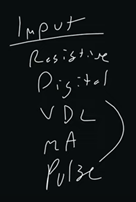
So, resistive element quite simply, you just complete a circuit with the resistive element in the middle of it. That resistive element whether it's a 1k nickel or a 10k type 2 or type 3 thermistor, those are going to sense temperature, typically.
Digital is typically an ON/OFF state, so this would be something like a contact closure, where you are either sensing resistance or you're sending a 5-volt DC signal through this contact closure. As you sense that signal, the controller knows that the state has changed from either on/off open/shut, etc. These are used for end switches, like on dampers, for fan status with flow switches. These are also used as auxiliary inputs from safeties, like low-temp safeties, etc.
Volts DC is another one, and it is polarity sensitive. It’s very similar in that you route one side of the inputs to the input side and the other side of the input to the common side. You may have to power this sensor externally, with an external transformer. Sometimes, the controllers actually have their own power.
Milliamp is very similar in that you pretty much wire it up the same. There is a little bit of nuance on some controllers that involves resistors that involves doing things a little differently, but for the most part, is wired up the same as well as sourced. How you measure volts DC and milliamp is a little different.
Volts DC, you can simply measure across the contacts and say, “This is 5 volts,” whereas with milliamp you either need an amp clamp to detect that amperage, that heat, that current, or you need to measure that current, what is called in-series. So, volts DC you can measure in parallel, you can put your leads across the wires, your multimeter leads, and measure it. Milliamps you either have to have an amp clamp to sense the current or you have to measure what is called in-series, so you have to interrupt the wire and actually put your leads in between one side of the wire to the other side of the wire to detect that current.
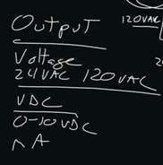
On the output side, we have three primary outputs:
- Voltage, which is either internally sourced or externally sourced. This is typically 24 volts AC, although it can be 120, but you don't typically route that through a controller. That is going to enable those coils, it's going to energize those coils to affect those contact closures.
- Volts DC, which is commonly used for a proportional valve actuator, or for a VFD control signal. Typically, 0 to 10 volts DC, polarity sensitive, used to drive VFDs, used to basically give a proportional, a variable control signal, to drive a device.
Milliamps. The big difference between volts DC and milliamps is that with volts DC, those tend to be shorter runs that are not prone to electrical interference. Milliamps tend to work well with longer runs that are potentially subject to interference.
That's because current, going back to Ohms Law, is created by voltage divided by resistance, whereas voltage is created by current times resistance. So, as we have that resistive effect, we are going to see more and more that we have some issues with our faults. We're also going to have signal degradation from just noise in general, over a longer distance.
Now, polarity. When we're using volts AC, we're using what's called alternating current. If you think about a battery, a battery has a positive and a negative side on it. So, what happens is the electrical, in the case of AC, it alternates between positive and negative. So, it's called alternating current. If you were to plug in an AC circuit, it's what's known as polarity insensitive, meaning if you hook up the positive side to the negative side or the negative side to the positive side, it's not really going to matter.

Whereas if we use direct current, we are doing a direct current, which is going to look more like a block on an oscilloscope, and our positive will be positive and our negative will be negative. If we crossed those wires, we are going to cause the signal to basically be inaccurate and improperly controlled and cause all sorts of issues. So, we need to be cognizant of the polarity sensitivity of volt DC wiring.

Continuing right along, the last thing that I will cover in regard to electrical concepts is going to be just a little tidbit on controllers and amperage. So, on inputs and outputs, controllers have amperage ratings. Remember, amperage is heat, amperage is current, and if we have too much amperage, we can damage our internal components to our controllers. So, we need to be cognizant of the amperage ratings of our inputs and outputs when we attach devices to them on the controllers, so that we don't damage the controller.
This becomes specifically important when we are using an externally sourced power and routing that through our controller output. So, if we have a relay output inside our controller, and that relay opens and shuts inside our controller, then we need to be cognizant of the amperage rating for that output so that we don't put too much amperage through that output. That can cause the controller to be damaged, sometimes permanently.
So, there you have it, some electrical concepts. This is by no means a sweeping electrical course, but this should give you some understanding of baseline terminologies. If you do want to dive deeper into these electrical concepts, we have a much more formatted and structured course on wiring and installation of control systems, inputs, and outputs. You can check out our BAS Installation & Configuration course.
As always, if you have any questions, please do not hesitate to ask. I'd love to answer your questions. Thanks a ton and take care.

.png)
.png)
