


Hey folks, Phil Zito here and welcome back. In this post, we are going to be diving into PID loops, or as I like to call them, PI loops because the reality is, we very rarely use derivative in building automation. So, by the end of this post, you will have an understanding of what PID loops are, what proportional, integral, and derivative do, why we use them, and you will have an easy way for setting them up.
It still amazes me to this day how many very experienced folks struggle with PID loops. How it seems to be this kind of black magic, mystical art that is tuning PID loops, when in reality, it's not that difficult. So, we're going to be looking at the cruise control model. There are many other models, and this is definitely not a scientific model, but there's all sorts of models and approaches to tuning PID loops, and I find them to be unnecessarily complicated. So, we are going to be looking at, what I view, as a very uncomplicated way of tuning PID loops.
Let’s dive in. For the sake of simplicity, I’m going to refer to these as PI loops. I don't believe in using derivative in about 98% of the situations you're in. It just does not make sense. It adds a complicating factor. What I hope you'll see at the end of this post, or by the middle of this post, is that the majority reason why people struggle with PI loops is because they don't know how to calculate proportional.
So, what happens is, imagine you're in a car, and this car is driving down the road, and it comes to a hill. This hill is going to introduce resistance, it's going to introduce what is called error to your control. What's going to happen is, let's say your car is supposed to be maintaining 55 mph: that's its setpoint. As you start to go up this hill, what is going to happen is the car is going to slow down to maybe 45 mph, which means your engine needs to increase. Your engine is your output. Well, what happens is there is a proportional difference between your actual desired setpoint and your process variable: you're actually going 45 mph and you desire 55 mph.
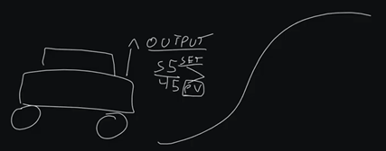
So, there's a difference, we have what is called an error, and that error in our case is 10 miles per hour. Now there is a proportional response to this. As we increase our error, our output should increase proportionately. On direct acting loops, which means as error increases, the output increases, there should be a proportional response. This proportional response is our P value.
What happens is, as we increase our error, which is difference between setpoint and process variable, we should naturally have a proportional output response. Now, if we have a proportional output response, but we're still not getting to setpoint over a period of time, that's when we introduce an integral value. That's our I, and integral meaning time. So, over a period of time, we are going to add more to our output.
So, we have a proportional response to our error, and then as our error maintains over time, we have an integral response. So, our equation kind of looks like this:
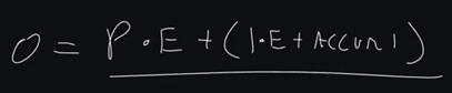
Output = P x Error + (I x Error + Accumulated I)
That is our equation that we're primarily concerned with.
Now, for those of you who are still confused and are thinking this makes no sense, don't worry. It will make sense by the end of this post.
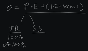
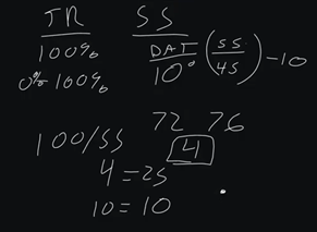
The biggest area people get wrong is this proportional response. So, what we want to do is, we want to figure out two variables: our throttling range and our sensor span. Fortunately, for us, our throttling range is almost always 100%. There are scenarios where it's not 100%, but I'm not going to cover them in this post. 100% is typically our throttling range.
Okay, what does that mean? That means the range of the output, it's full throttled range. So, if I go from stop, to 100%, or fully go, that in most cases, it's going to be 0 to 100%. That'd be 0 to 100% valve command, 0 to 100% VFD command, or in our case of our motor, 0 to 100% RPM.
Now, we have our sensor span, and this is the controllable range of the sensor in which we are having a response. So, what I see a lot of people do is they will try to set up a PID loop for maybe DAT (discharge air temp), and we know that DAT maybe has a 10-degree range. So, our setpoint may be 55, and we know that we drift between 45 to 55.
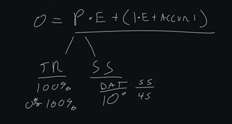
Now I'm just using simple numbers here, because in actuality, 55 would actually be the middle percentage, and we would do like 60 to 50, but that's more advanced. So, we have a 10-degree sensor span.
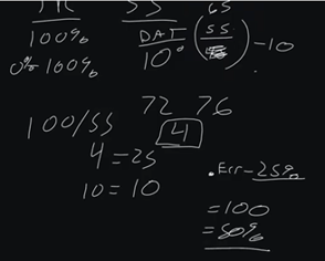
Maybe you're in a room, you're in a space, and you have 72 degrees and our max cooling of 76. So, we have a sensor span of four. Now what we do is we take the throttle range of 100% and we divide it by our sensor span, which in the case of our room is 4. In the case of DAT, 10 divided into 100, so that would be 10. So, 4 would equal 25, and 10 would equal 10. So, our P for room control would be 25.
That means for every degree of error, we would get 25% output. So in theory, if we were at 76 degrees and our setpoint was 72, we would have 100% damper command on our VAV box. So, in theory, if we're at 65 degrees DAT, and we're trying to maintain 55, we would have 100%. But if we're at 50 degrees DAT we would have a 50% output.
So, this is how you get your P value, and your P value, if you get anything right in loop tuning, it's getting that initial P value. If you get that initial P value right, you're going to be so far ahead of pretty much everyone else.
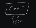
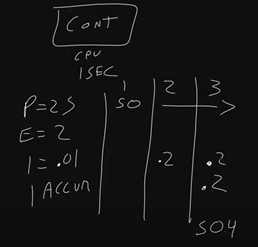
Now we have this I value. We have to understand how I accumulates. Inside a building automation controller, we have a processor, we have a CPU, and that CPU processes all of our logic. Typically, in building automation, the standard is to process logic once a second. So, our loop processes once a second. So, our I value processes, once a second because it is going to process every time the building automation controller runs through the loop.
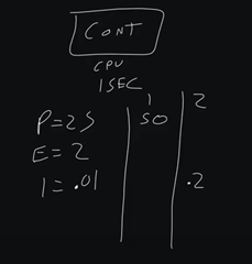
So, in our scenario, we have a P value of 25, because we're doing room control. We have an error of 2. So, our initial output on cycle one is going to be 50%. On cycle 2, which is cycle 2, we have our I value that we introduce.
This is why I always recommend starting with a small I, so if we do a 0.1, that will give us an I value of .2. So, .2 is going to be our initial I value, and that's going to be our I calculated.
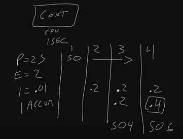
Then we have our I accumulated. In cycle three, we're running it again. We're three seconds in and we still get that error. So, we're still 50% across the board in response to our error. We add another .2, but we also have our I accumulated from before. So now our resulting loop is 50.4.
If we go to cycle four, we now have an accumulated of .4, we have an I calculated of .2, and we get 50.6. This is how PID loops work. Until we actually start to get a negative error, we are not going to have this accumulated I go away.
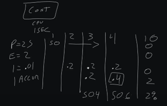
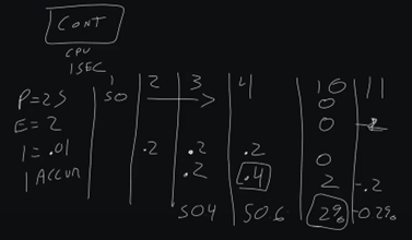
So fast forward to maybe cycle 10. We’re at accumulated 2. But let's say our error now is 0. So, we have a 0 proportional output, we have 0 error, we have 0 calculated I, but we still have 2%. That's why you can be in a 0-error scenario and still have an output on your PID Loop.
However, when we move into a negative scenario now, so we have a -2 error, that is where we actually will see our I start to reduce. So, we'll have our accumulated I and -2 error x .01. At cycle 11, we would actually get a -.2, so we would have 0.2% negative as our output.
Now, certain loop manufacturers keep this from happening. They keep from what's called integral wind up and integral wind down. In older controllers, this was a big issue in that you would have an I accumulate, and it would wind past 100% load. You would have a spun-up loop, and this was notorious for happening when a piece of equipment was off, but the PID Loop was still trying to control it and it never could. You would have I accumulated, or an ID cumulated decreased, basically a negative or positive accumulated I. Then you would have to reset the PID loop.
That has largely been dealt with, with most manufacturers. They put in thresholds so that you can't go above 100% accumulated I can't go below 100% accumulated I. This is why you actually start with a small I. So what you'll learn over time, if you get proportional right, then how do you calculate I?
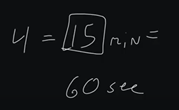
Well, how I like to calculate I is I look at the speed of change. So in a space, we typically have 4 air changes in a space. That's by the way, where our 15-minute trend interval tends to come from. Some folks will say our 15-minute trend interval comes from data capacity, and that is true, but how did they find that data capacity? If you divide 4 into 60, you get 15.
Since trending zone temp was the most common trend in building automation, like you may have one discharge air temp, but you have 100 zone temps, we would trend them based on air changes. Since 4 air changes is the most common air changes for space per hour, then we came up with this 15-minute trend interval.
Well, 15 minutes, by the way, as well is an air change. It's when we reasonably expect our space to be at setpoint from a complete error scenario. So, we go from like 76 to 72, we reasonably expect that we can achieve that within 15 minutes. So, we have to say, we want our I to accumulate over that time period.
So, what I've done, and this is total swag, Phil Zito experience here. There's no real science behind this, but what I've done in these scenarios is I look at whatever my control is. So, in the case of a space, it’s typically 15 minutes, and in the case of discharge air pressure on an air handler, that's typically 60 seconds. I look at that, and I identify that my I, I need it to go across this range in that amount of time, and that's how I come up with kind of an I value.
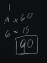
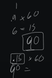
So, if I know that an average loop runs every second, so 60 seconds, that gives us 60 accumulations. If I did .01 x 60, that gives me 6. So, every minute, I would get six accumulated I. So, if I get 6 accumulated I, and this is assuming a pretty basic error of 1. But if I get a 6 accumulated I over that, if I times that by 15, that gives me right about 90. So, pretty close to 100% I that I can get over a 15-minute period.
Now, if I go to 60 seconds, that's not going to get me there. So, that's why you typically will see like .1, which .1 x 60 would put us at 60. So, like .15, would be a starting integral point for a discharge air pressure loop. Over 60 seconds, we would actually get 90 accumulated I, assuming a basic error of 1. Right?
So, that's kind of how in my career I've come up with my range of I for my building automation PID loops.
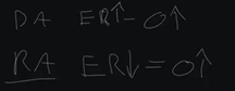
Now I want to talk about a direct-acting versus a reverse-acting loop. A lot of people get this really complicated, but it's actually very simple. Direct-acting means as error increases, output increases. Reverse-acting means is error decreases, output increases.
So, what would scenarios be where we have a direct-acting versus reverse-acting loop?
A direct-acting loop scenario would be like zone temp, discharge air temp, etc. Reverse-acting loop scenario would be something like, as pressure decreases, because if pressure increases, we actually want to lower our output. So, as we get a lower error, as we decrease in the case of discharge air pressure, or hot water, where we drop below setpoint, those would be scenarios where we want to increase our output, reverse-acting loop.
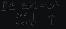
Cooling, space temp, etc, in the case of cooling, these would be scenarios where we want to increase our output as we get too high.
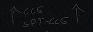
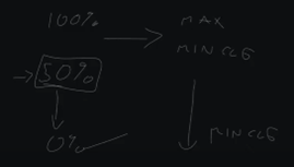
Now the next thing I'm going to say about this is what is called a stop or startup value. Not every PID Loop manufacturer supports this, but where you would do this is when you want to preload something. So oftentimes in space control, we'll do a preload of 50%, because we have minimum ventilation requirements for spaces when they're occupied. So, we will preload our PID with 50, and then from 50% to 100%, we’ll actually use like a scalar object, and this will throttle us between max and min cooling. Then 50% to 0%, this is pretty much just min cooling right here, and then 50%, we adjust working with the balancer, etc to get whatever that is.
This isn't a hard and fast rule. Some folks don't do this for their PID loops. Some folks will actually have a PID loop that’s 0 to 100, and then it'll go into two scalar objects, one for a heating mode and one for cooling mode. Others will have a temperature driven heating and cooling mode that goes into a switch that then switches CFM setpoint.
There's a variety of different ways to approach this in your setting up of loops. Just realize that startup value, that preload value, is a potential approach to things. I don't like to use it; I personally like to have a single purpose loop. So, if I'm going to use a loop for cooling, I have a loop for cooling. If I'm going to have a loop for heating, I have a loop for heating, and I tune them accordingly, because the rate of transfer, as well as my sensor span in a heating scenario is different than my cooling scenario.
So, I like to have two different loops, and then I like to use a numeration, like switching between cooling or heating or ventilation mode, and then controlling my loops accordingly. That's how I prefer to program. That is my approach. That's not to say it's the only or the right approach. It is my approach.
So, there you have it. This should give you kind of a baseline understanding of PID loops, or as I like to call them, PI loops. I hope you feel more comfortable after reading this. I hope this feels less mystifying. I feel like people try to validate themselves by making this seem way more complicated than it actually is, and my hope is that after reading this, you feel very comfortable.
If you still are looking for support beyond this, I would encourage you to check out our PID Loop Tuning Course. As always, make sure comments and ask questions.
Thanks a ton, and take care.

.png)