

Central Utility Plants are the life blood of an HVAC system. This series will begin to give the reader an understanding of what Central Utility Plants are and will act as a spring board from which we can launch into deep control discussions.
This series will cover:
- Central Plant 101
- Pumping Systems 101
- Condenser Systems 101
- Free-Cooling Systems 101
This article is the third article in the CUP series. This article is not intended to give the audience formal knowledge around condenser systems design. It is rather designed to help the reader fully understand how condenser systems work to evaluate designs and troubleshoot condenser related issues.
If you recall the refrigeration cycle from my earlier article Central Plants 101 you will remember that the heat absorbed on the expansion side of the loop must be transferred and ultimately exhausted on the evaporative side of the loop. This is essentially the function of condenser systems. While not specific to Central Utility Plants (CUP)'s, Condenser systems are most commonly found in Central Plants under the guise of Cooling Towers and Condenser Water Loops. This article will explain to you the basic design and function of the loops, multiple methods and theories around cooling tower design, and the dynamics that indicate cooling tower failure.
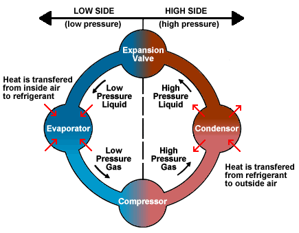 The Refrigeration Cycle
Way Back When.....
I Still remember meeting with the mechanical contractor on a Hot 100+ Degree summer day in Dallas Texas. According to the contractor we had entered the wrong pressure setpoint on the condenser loop and this was causing the pump to break its seals causing water to spray all over the mechanical room. Well after hours of adjusting setpoints the issue continued. I pointed out that maybe, just maybe there might be an issue with how the condenser loop was designed. Soo... we went out and traced the loop, sure enough there was a three-way bypass valve in order to bypass the open cell (more on this later) towers. However, the pipe-fitter had neglected to pipe the flow over the tower and rather had the pipe simply draining the tower when the loop was at full bypass.
Well long story short this was causing a vortex in the tower and was creating a giant air bubble in the loop. Thus whenever the bypass valve opened and water began to flow the air bubble would have nowhere to go and would cause the pump to expel water. That was a long day of tracing pipe and arguing with a mechanical contractor but it illustrates the reality of why BAS professionals really need to understand condenser loops.
Condenser Loop Types
Condensing systems, and more specifically cooling towers are used with water-cooled chillers, plate frame heat exchangers, and water-cooled DX Units. The purpose of the condenser is to extract heat from a cooling loop and to transfer that heat to another medium (water, air, ground, ect). There are typically three main types of condenser loop systems:
- Cooling towers
- DX Loops
- Heat Exchangers
In this article we will discuss Cooling Towers.
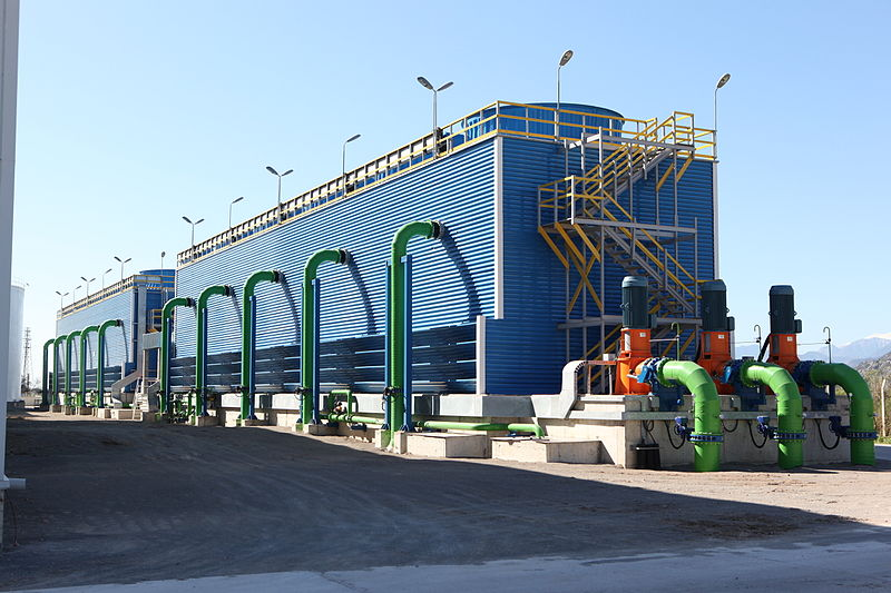
Cooling Towers
Design
To Fan or not to Fan that is a Question
Cooling towers rely on airflow to transfer heat out of the condenser water and into the air stream. There are three main methods of Air Flow: Natural Flow, Forced Draft, and Induced Draft.
Natural Flow-
People Say I've Got a Natural Flow
Natural flow is not the main method of airflow design in most commercial or industrial buildings. You mainly see natural flow in power plants or systems that have large stacks that let heat naturally rise and transfer inside a tall exhaust stack. This is the method you need to be least concerned about.
Forced Draft-
I can be rather forceful
Forced and Induced Draft seem similar at first read but don't worry there is an easy way to remember the differences in the two systems. When you force someone through a door you are pushing them through the door way. Forced draft works by putting a fan at the intake of the cooling tower and effectively pushing the air through the tower. Now the happy little air particles can dance around and do the BTU shuffle inside the cooling tower as they transfer BTU's from warm condenser water to the outside air via evaporation.
In Judo it takes more energy to push someone then it takes to pull them and use their momentum. Because of this Forced draft systems usually need to be designed with larger fans that are capable of higher horsepower. The con of this is that your fans need to be bigger, where as the pro is that because of the larger fans you can have your tower in confined spaces that require higher pressure draws due to the smaller air volume!
Induced Draft-
People say I suck
Going back to our door analogy induced draft systems pull airflow through the tower. Induced draft takes advantage of pressure and temperature laws in order to allow the airflow to work for the fan rather than against it. The Induced draft tower is the reverse of the Forced draft tower. If the Forced draft tower is trying to pull the fat guy through the door the induced draft tower is waving a doughnut in front of him and giving him a gentle pull using the force of his 400 lb frame to get him to come inside. Induced draft towers can have smaller fans but require greater volumes of air. If the guy coming in the door is a 80lb stick figure then the induced draft fan has to work a lot harder because of the lack of momentum.
Let's Confuse you a Little bit More
A+B=C unless B+C=A or D or E....
So your system has a natural flow or mechanically induced draft, that's great. What do you do with this draft? Why do you need it? Well if you remember our friend the psychometric chart, as you add moisture to dry air that water cools the air because the BTU's are leaving the water and "saturating" the air.
If we get rid of BTU's we are getting rid of heat! Less heat equals cooler water. Thus we have two main ways of getting the air to absorb the heat from the return water.
Let it RAIN!
When we let the water rain down "over the top" of the tower we are creating a stream of water that the air will flow through. Sometimes this looks like water running down rivets on the inside of the tower. Other times this looks like the water simply dripping into the tower basin (bottom).
Push that water Through
If you push water through the basin of the tower and then use fans to force a draft of air over the surface of the water then the BTUs in the water will be absorbed by the air. While not as efficient as making it rain, this still will provide some BTU transfer. Most designs use "through the tower" instead of "over the tower" when there is a low load condition.
More Design Fun!
Oh you use your cooling tower to water your parking lot, that's smart ...
In addition to airflow design, Cooling towers consist of a single or multi-cell structure with a common or isolated sump. Depending on the design the tower can consist of a single cell or multiple cells. The easiest way to think of a multi-cell tower is to think of a multi-chiller plant. If you have variable loads you want to be able to use the least amount of chillers to reach 42 degrees as possible. If I have a single 2000 ton chiller and my load is 200 tons then I will be cycling that chiller like crazy (think turning on and off the chiller rapidly). If your tower has to maintain 85 degree condenser water and it is sized for a 2000 ton load you will be ramping the tower fan, pumps, and bypass valve like crazy. Or.... you could simply split your tower into multiple cells and divide the load into smaller towers.
The operation of the tower during a normal cooling season OAT>68 degrees is as follows.
- Upon initiation of the cooling system. The cooling tower will control to 85 degree supply water (adj).
- The cooling tower will initially open the cooling tower bypass valve to control temperature or head pressure.
- Then once the valve is 80% open and setpoint is still not reached the fan's will begin to ramp up with a minimum speed of 30%.
- Upon reaching 80% (adj) the cooling tower if it is multi cell will begin to ramp up the second fan and the two fans will then track to the same fan speed in order to control to 85 degree adj.
- Reverse the sequence to stage down
Depending on your refrigeration and chiller design colder water can be more efficient due to being able to absorb more BTU's and provide a more efficient heat transfer. The typical setpoint is 85 degree adjustable but some chillers are now accepting 55 degree condenser water setpoints.
The key point of the sequence above is that first we introduce flow to the tower WHEN WE ARE ABOVE THE OAT ENABLE SETPOINT (don't want to freeze any pipe, well unless you are in the disaster cleanup business) and as the return water at the chiller heats up we begin to ramp up the fan speed . Now if you have a constant volume fan or do not have a bypass valve then you simply turn on the pump initially and if temperature continues to rise you will turn on the cooling tower fan. Typically a sequence block with a minimum on time but no minimum off time is acceptable for controlling the tower.
Conclusion
So do you feel like you better understand how Condensing Systems work?
What were your thoughts on this article?
Did anything stand out to you as particularly insightful?
Let me know in the comments below!