
Central Utility Plants are the life blood of an HVAC system. This series will begin to give the reader an understanding of what Central Utility Plants are and will act as a spring board from which we can launch into deep control discussions.
This series will cover:
- Central Plant 101
- Pumping Systems 101
- Condenser Systems 101
- Free-Cooling Systems 101
This article is the second article in the CUP series. This article is not intended to give the audience formal knowledge around pump design. It is rather designed to help the reader fully understand how pumps work in order to evaluate designs and troubleshoot pump related issues.
This article will cover:
- Key Terms
- Pump Design
- Pump Types
Key Terms
The following are some key terms that you need to understand as we move into pump theory and design:
- Open Loop System- An open loop system is exposed to the atmosphere. An example of an open loop system is a condenser water loop with an open tower.
- Closed Loop System- A closed loop system is isolated from the atmosphere and should have no external or internal leakage of water or air.
- Pump Curve- The pump curve shows the operating conditions for a pump in specific design conditions. This is the single most important chart for you to understand in pump design. Selecting the correct pump will allow you to meet your design conditions while operating at peak efficiency. We will cover pump curves in greater detail later in this article.
- Suction Head- The suction head is the sum of the static and the velocity head (For calculations refer to link).
- Net Positive Suction Head (NPSH) - The NPSH is the difference between the Suction Head and the Liquids Vapor Head (For calculations refer to link).
- Efficiency- The efficiency of a pump is the HP into the pump versus the HP out of the pump.
- Impeller Diameter- This is the width of the impeller and is typically used as a key factor in sizing pumps.
- Flow- This is rate at which a fluid moves through a pump. This is typically GPM or gallons per minute.
- Parallel Pumping- Parallel pumping is where any individual pump can serve a device.
- Series Pumping- Series pumping is where a specific pump is dedicated to a specific device.
Pump Design
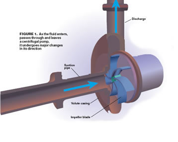
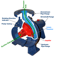
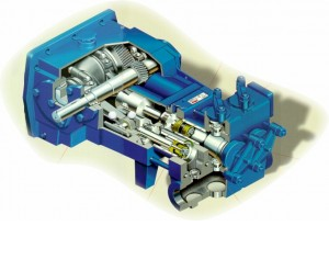
Pumps are designed to move water throughout a piping system. The cross section of the pump is for a centrifugal pump. You will notice that water is coming into the pump on the horizontal plane and is flowing into the impeller. The impeller is then driving the water flow upwards into the vertical plane.
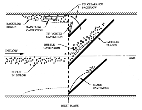
Now, not all piping is configured this way but the general rule of thumb is that you need to have 5 to 10 pipe diameters in length between the inlet/outlet of the pump and the first bend. This is to account for cavitation which is visually shown below and will result in uneven distribution of water and the build up of air bubble upon the impellers. If your feeling frisky you can read in great detail about cavitation here.
There are various types of pumps and they have different effects on design variables, but the fact remains they exist to move water. When designing a pump, we need to understand why we are moving the water and how much we need to move. Typically, we are moving water to transfer BTU's from one source to another.
In the case of chilled water we are moving water throughout a system to absorb BTU's from another device an example of this would be taking heat out of an air stream via a chilled water coil. When you are selecting your pumps, you need to account for several variables. The main variables to account for are:
- Environmental and mechanical conditions- You need to take into account if you are pumping water up a multi-story building and in which environment are your pumps going to be running.
- GPM requirements of the equipment- For this you need to account for the GPM of all devices that are utilizing the water.
- Heat transfer or Delta T- This will help you understand how much your flow rate needs to be in order to effectively transfer the proper BTU Load.
- Loop type- Are you using a Single loop with constant volume or are you using a Primary/Secondary loop with variable flow and mixing valves?
A great article that was published in the ASHRAE Journal about designing central plants is posted here.
Pump Types
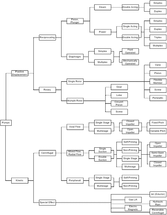
As you can imagine from the diagram above, I could literally fill pages going through each type of pump. Fortunately for you, there are only three types of pumps I am going to discuss. The three types of pumps I will discuss are Centrifugal, Reciprocating Pumps, and Rotary Pumps. In order to further understand the difference between positive displacement pumps and kinetic pumps, refer to this detailed article here.
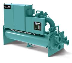
Centrifugal Pumps
Centrifugal pumps are the big daddy of pumps (yes, that is a technical term). They have a capacity of more then 100k GPM and can be equipped with variable speed drives. If you need to move a lot of water in a medium pressure environment, a Centrifugal pump is the pump of choice. However you must be aware that a Centrifugal pump is limited in the pressures it supports and it significantly looses efficiency when you utilize it above 1000 psi.
A centrifugal pump utilizes an impeller to pull water into the suction side of the pump. The impeller spins and literally scoops the water up and pushes it out the pressure side of the pump. The action and angle of the impeller is typically engineered for the suction side to be horizontal and the pressure side of the pump to be vertical.
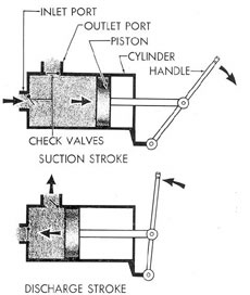
Reciprocating Pumps
While the Reciprocating pump does not have the high flow rate of the centrifugal pump, it makes up for its lower flow rate by having a significantly higher pressure capacity (100k PSIG+). When you need to move dense liquids or you need to pump against atmospheric pressure, you can utilize a reciprocating pump to overcome high pressure scenarios. A Reciprocating pump is great for pressures above 1000 psi that require a medium to low flow rate. Additionally, if you are going to be moving fluids such as oils or other viscous fluids, then you will want to utilize a reciprocating pump. Quite frankly, I can count on one hand the amount of reciprocating pumps I have seen in chiller plants.
A Reciprocating pump is mechanically quite simple. The pump utilizes a piston driven forward inside the cylinder by the motor the action of retracting the piston pulls liquid in the inlet and the contraction of the piston pushes the liquid out the outlet port. The lack of complex parts allows the reciprocating pump to be utilized for many corrosive liquids.
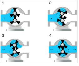
Rotary Pumps
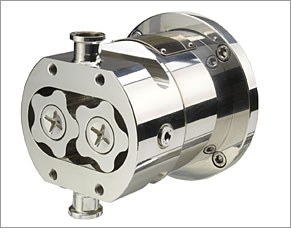
The rotary pump has a low flow rate and does not have a high pressure rate. The rotary pump makes up for its lacking by being a highly efficient pump when it comes to viscous liquids. When you need to move viscous liquids, you can rely on a rotary pump to provide optimal performance. While not very common in central plants, you will see rotary pumps in process control and in some treatment facilities on processed water.
A rotary pump or a rotary vane pump is like most positive displacement pumps in that it positively displaces the water. Unlike a Reciprocating pump, which utilizes a piston, a rotary pump utilizes vanes that trap the water between the two vanes and move the water from the inlet side of the pump to the outlet side of the pump. These pumps are often utilized in situations that require a pump to handle highly viscous fluids that do not high pressure and flow requirements.